
The PSP was probably the last handheld I owned when I was a kid. It was Sony’s first entry into the handheld market to which they have since departed. I recall all the mods that could be performed back when I crawled forums reading the latest and greatest.
One unique challenge the PSP faces is the fact that even to this day you cannot dump a PSP disc exactly sector by sector, even with current dumping tools you simply can’t. I’m also quite certain UMD movie discs can’t be dumped properly. So the highest priority in this project is to retain the UMD drive if a digital video mod is implemented.
So at a high level, we have the following requirements:
- Digital RGB to digital video serialization to 1080p
- Retain UMD drive in a case design
- PS2 Controller (SPI interface) to PSP for button pressing.
For the case design, I will likely team up with someone else once the project is closer to fruition. The SPI to PSP bridge will likely be a microcontroller such as the popular RP2040. I won’t use the FPGA to perform that as I will be potentially short on pins. Coding on MCU itself will be quite a project in my skill range.
The PSP-1000 doesn’t have available schematics but luckily the datasheet for the screen that was used is floating around.

So a few things to note is that it is 24-bit parallel RGB. The NGPC was 12-bit parallel RGB. This consumes more pins on the FPGA of course and the FPGA I have chosen is a bit pin-deprived but the security for it is in my opinion very good.
The PSP has a 2.5V logic BUS for the screen. Generally, with embedded systems, you’ll find lower voltages so there was no surprise there when confirming the 2.5V logic on an oscilloscope.
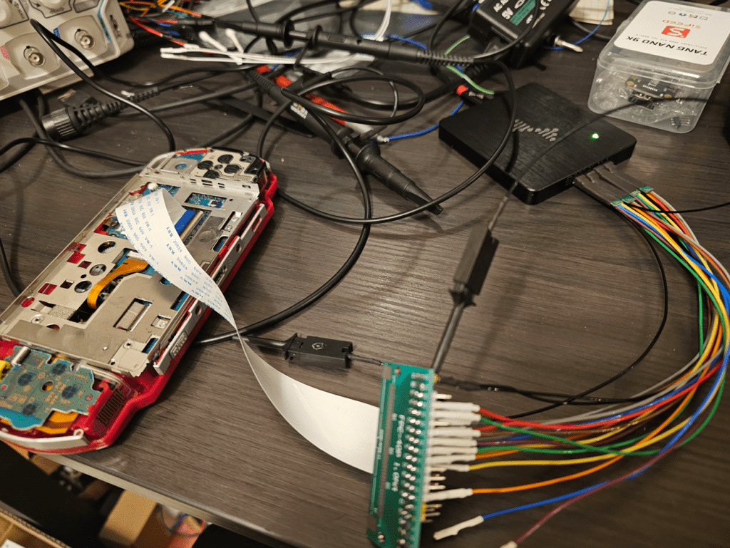
I was able to get a 40P ffc breakout and ffc cable to view the digital RGB
After fiddling with DSView I was able to capture everything successfully. To do this properly, I had to set the DSView trigger voltage to 2.0V. 2.5V wouldn’t cut it. Below is a snapshot of two whole frames captured in 50ms.
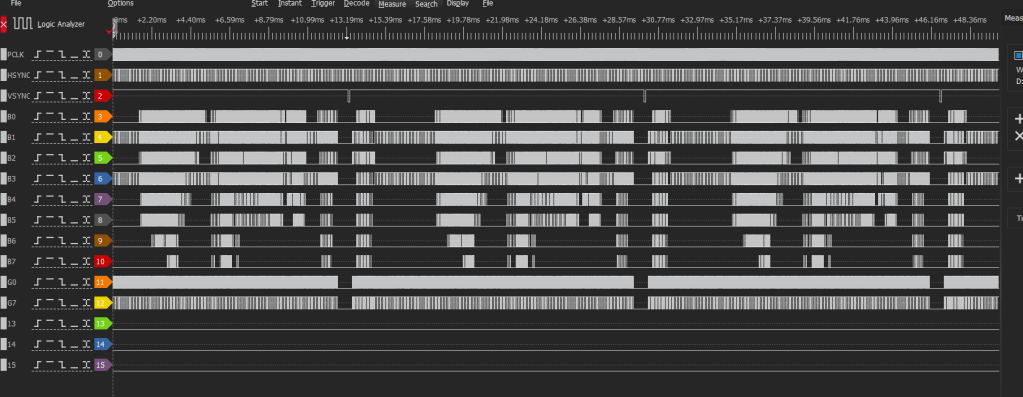
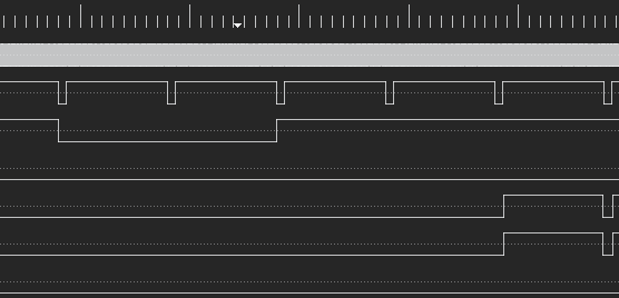
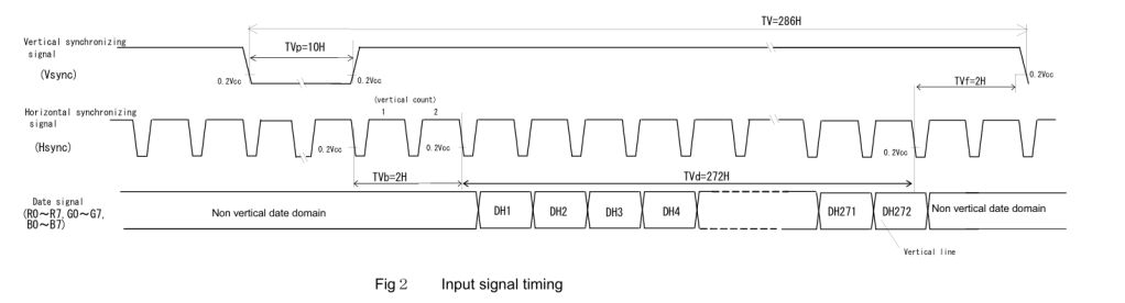
First thing to note is the front porch. The datasheet says the frontporch should be approximately 2 pulses but as we see the VSYNC (third row) pulse low there are actually two pulses before the new line denotes. I previously said 3 rows on Twitter recently but I was quite tired that evening. But now we know the FP is approximately 2 which will be important for building a state machine to control pixel input into a line buffer. The snapshot on the datasheet below also confirms the FP as being 2.
The back porch in this photo we can see is approximately 10 pulses. So 10 for BP. I previously thought this was 11. There are also two extra pulses during the VSYNC blanking period so I’m uncertain if that makes the total 13 or not. I’m honestly not certain.
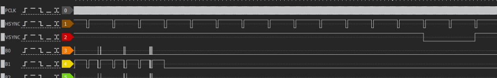
The PSP-1000 screen runs a 24-bit RGB interface at 480×272 resolution. The PCLK runs at 9.0013mhz, the Vsync runs at 59.9406hz and Hsync runs at 17.1430khz. After enough settings changing in DSView, I got a clear and accurate capture of the pixel clock.
Things to do:
- Double check FP, BP and how many HSYNC pulses are in the VSYNC pulse window
- Determine how many pixels are actually on the screen and then off-screen via counting PCLK pulses on one line
- Verify if the i2s audio is on an FFC or not even available. If not, then some audio ADC has to be performed and I think that would be solderless since it’s just a speaker. Then the whole kit would be solderless actually.
With those 3 tasks being completed, I can create an FSM to capture the screen data. The idea is just like NGPC; capture one line, pixel and line multiply as much as possible to fit the new screen into a 1080p digital video window.
At this time I have already purchased some HDMI development boards from Taiwan and due to the New Year, I can’t really proceed and test more. NGPC has a higher priority though. So for now until I have a T20 (Efinix) development board designed I will stick to the DE0 board from Intel. Side note the T13/T20 has enough LVDS pins to serialize the pRGB from NGPC but not the PSP. Hence I will be very pin-starved and need an MCU for controller transcoding for this project.
I’ve also had requests to check the PSP-2000 and PSP-3000. There are a few problems with them. For one I need datasheets for both LCDs those units used and I also suspect the PSP-3000 would require MIPI deserialization or specifically: MIPI RX to Byte, and then Byte to Pixel. As I understand the only affordable FPGA that currently offers this is Gowin and I would like to try to not be stuck on them because of their lower yields for high-speed grades (byte clock of 425mhz I think is required for deserialization). MIPI specs and critical information are paywalled and I don’t have access to them. With funding of other projects when they’re complete I can take a look at them eventually. I really do need datasheets for those screens before taking those on.

Leave a comment